Principles of Operation
A turbine flowmeter consists of a rotor mounted on a bearing and shaft in a housing. The fluid to be measured in passed through the housing, causing the rotor to spin with a rotational speed proportional to the velocity of the flowing fluid within the meter. A device to measure the speed of the rotor is employed to make the actual flow measurement. The sensor can be a mechanically gear-driven shaft to a meter or an electronic sensor that detects the passage of each rotor blade gen- erating a pulse. The rotational speed of the sensor shaft and the frequency of the pulses is proportional to the volumetric flow rate through the meter.
Description
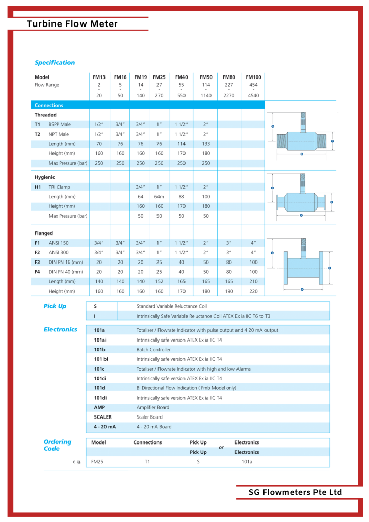
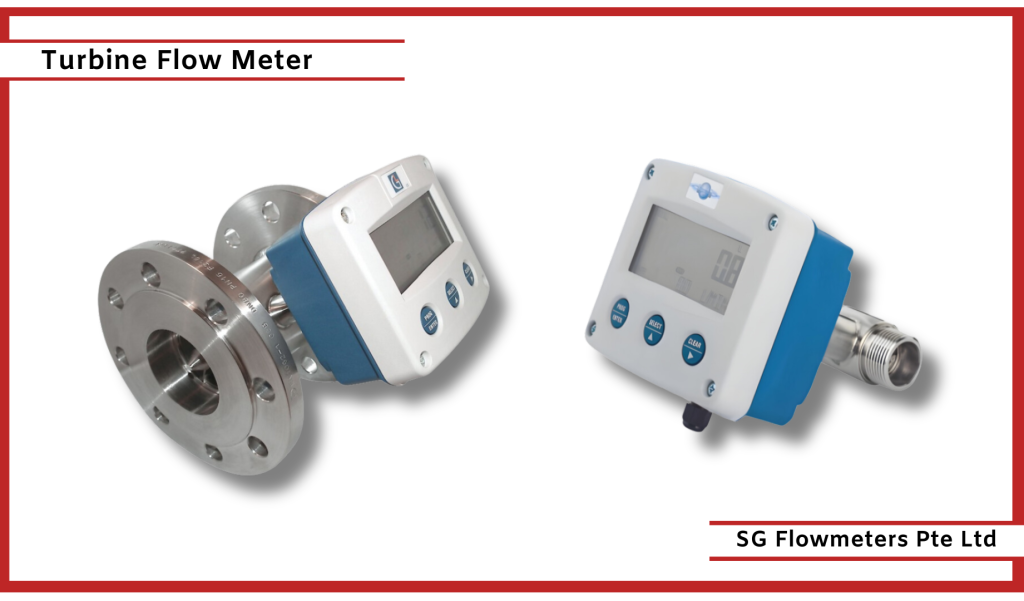
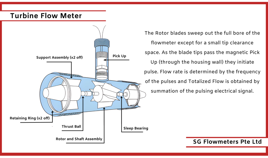
Consisting of three component assemblies, fitted inside a stainless-steel body (locked with retaining rings), which has a Pickup (variable reluctance sensor) fitted and come in a range of threaded, flanged and tri clamp styles.
The Rotor and shaft assembly (1 off) which is mounted in sleeve bearings, fitted inside Support assemblies (2 off) is turned by the kinetic energy of the flowing guild at an angular velocity, which in the linear range of the Flowmeter is proportional to the mean axial velocity of the fluid.
The Rotor blades sweep out the full bore of the flowmeter except for a small tip clearance space. As the blade tips pass the magnetic Pick Up (through the housing wall) they initiate pulse. Flow rate is determined by the frequency of the pulses and Totalised Flow is obtained by summation of the pulsing electrical signal.
Specifications
- Working Temperature: – 50ºC to + 282ºC
- Accuracy: + / -0.5% of reading overflow Range
- Repeatability: + / – 0.15% of reading
- Pressure Drop: Less than 0.5 bar at Maximum Flow
- Materials: All 316 Stainless Steel with ANC1A Rotor
- Bearings: Wear Resistant Tungsten Carbide Sleeve
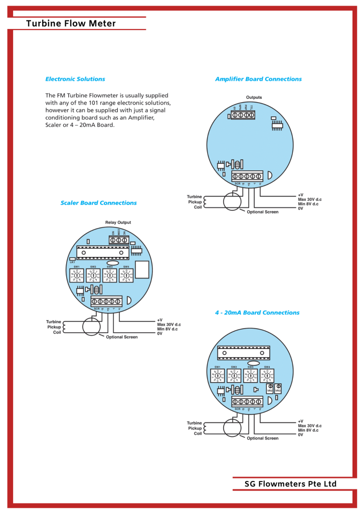
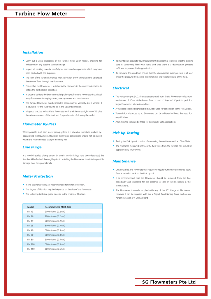
- Pick Up: The Lx variable reluctance sensor is hermetically sealed for resistance to moisture and can withstand repeated thermocycling. The magnet is resistant to demagnetization.
- Output: low-level signal that ranges from 10 mV to 1 V peak to peak. A screened twin core signal cable should be used for connection to the Pick Up.
For more information visit:
FEATURED PRODUCTS
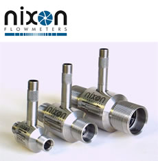
NT Industrial Turbine Flowmeter
The Nixon range of turbine flowmeters offers high accuracy and high reliability. Over 40 years, thousands of units have been sold to all classes of
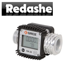
Digital Turbine Flow Meter
Digital Turbine meter for low viscosity fluids, easy to install in line or for end of line applications.
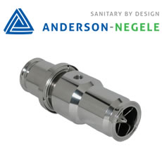
HM Turbine Flow meter
Anderson-Negele’s HM-series turbine flow meter is the solution for applications requiring an economical, accurate flow meter. Using the proven method of counting the rotation of

SERIES GT-TRG : STANDARD TURBINE FLOW METER
MULTIPLE FLOW RANGES .08 TO 5,000 GPM (gal/min) PRESSURE Working pressure up to 5,000 psi
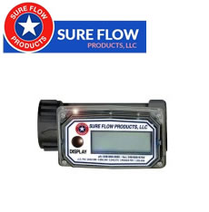
SERIES GT : TURBINE METER WITH DISPLAY
Full scale flows from 10 GPM to 200 GPM Connection Sizes: ½ inch to 2 inches
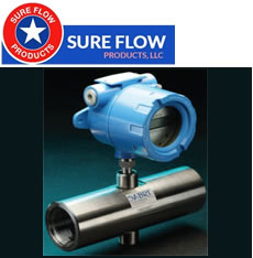
SERIES GT-TW :BASIC TURBINE FLOW METER
ACCURATE & RELIABLE The GT-TW Series turbine meter is accurate to ±1% of reading with repeatability of better than ±0.1%.

SERIES TT* : COST EFFECTIVE IMPELLER FLOW METER FOR LIGHT VISCOSITY FLUIDS
Full scale flow ranges from 15 to 50 GPM Connection sizes from 1/2-inch to 1-inch NPT or flange


